 .........
by Ironsides
[contributions from MAAC pilots Skip Pothier, John Hawkins, Gord Schindler, Jack Humphreys, Bill Shedden, Winnie Ambruch and Phil Peloquin]
Introduction
Before you start, it is strongly recommended that you read the overview on float flying entitled "The Basics of Float Flying". There are some concepts contained in this work that are essential to proper float design and installation. Perhaps the most critical is an understanding of the importance of the step and its relationship to the aircraft centre of gravity. If you get this part wrong, your plane will probably just become a fast airboat and never get airborne.
This article discusses the construction of foam core floats. They are the floats of choice because they don't sink. Built up floats with cracked balsa sheet have a tendency to fill up with water. Once the water hits the inner balsa there is little hope of repair. If the water gets into the float and you get airborne, then you will experience a very interesting test of your piloting skills as the water sloshes back and forth and takes the centre of gravity with it. How do we know - guess!
Caveat
Gord Schindler taught me the basics of foam core cutting. Bitten by the bug, Skip Pothier and I cut our first set of foam cores in my garage in late 2000. We learned a great deal from that tentative step. The following descriptions and diagrams are aimed at newcomers to the sport of float flying. The measurements given are not exact and are not intended to be used as "fool-proof" plans. Rather, the intent is to give insight as to how to approach the whole subject. The narrative gives an idea of what will work adequately. More experienced builders may have more elegant solutions.
Sources
You can obtain foam cores for floats from three sources. You can buy them pre-cut from a mail order house or a local hobby shop or you can make them yourself. For the sake of argument, it is suggested that the reason you make them yourself is for the pure joy inherent in any act of creation. In general, the floats you obtain through the mail or from your hobby shop will be of superior quality; the foam used will be something known as EPP (expanded polypropylene foam). This type of foam is made using very small, uniform beads and it is what is known as virgin foam. Of course, with the higher quality comes a higher price. The discussion that follows assumes that you want a set the floats that will work, that are inexpensive, and are relatively easy to construct.
John Hawkins of the Halifax Radio Control Club suggests that you might you check for floatation billets to get large pieces of foam? In some areas they are available in expanded polystyrene - bead board- and in extruded polystyrene as in the DowÔ line. You might be able to find a local building supply firm that will cut a billet of foam to the thickness you want. These 4' x 8' blocks come about 30-in. thick and are hot-wired to whatever thickness you designate. If a group from your club got together, you could order a block cut to the thickness you want. Look for "bead board" producers in your area.
If all else fails, an adequate type of foam can be obtained at any store that specializes in construction materials, such as Home DepotÔ. The material is the normal white insulating foam that comes in sheets of varying thickness and normally in sizes of two feet by four feet or four feet by eight feet. For most float projects, you will need foam that is six inches deep; unfortunately, that size is not common in construction material. Consequently, the best route to go is a 2-inch thickness using three laminations to achieve the 6-in. depth. The foam used for this type of insulating board is of fairly low quality, the beads are of varying thickness and generally are made from recycled material; consequently, it does not provide the clean cuts that one can obtain with EPP foam. But, given the fact that you are going to cover it all with balsa sheet, who will ever know?
Float Types
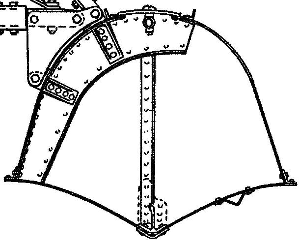
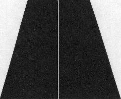
There are two basic float patterns that are common to radio control float flying. They are the Carl GoldbergÔ/Great PlanesÔ variety (left) and the classic EDOÔ style (right).
.........
It is suggested that the EDOÔ pattern is a bit more difficult and should be attempted only after the basic CG /GPÔ patterns have been mastered. In our hobby, floats are sized to match two-cycle engine bores of 25, 40 and 60 cu. inches. The 40 size, or 36-in. length, is the most popular. The bulk of this article will assume that we are going to make the basic 36 in. CG /GPÔ pattern. Afterwards, we will have a quick look at the EDOÔ style.
Click here to jump to the EDO style.
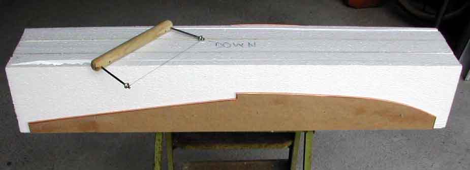
Hot Wire Foam Cutter and Power Supply
It is beyond the scope of this article discuss the detailed construction of the power supply and cutter, but the basics for a bow can be found in a number of places on the Net - just do a "Google" search. Notwithstanding, this link might be of use:
http://webpages.charter.net/rcfu/ConstGuide/FoamWing.html
Assuming that you have now constructed your power source, the basics of the hot wire cutter should be discussed. You will need both a long cutting bow (44") and a short cutting bow (8") for foam core cutting. The type of wire to use it is called "nichrome" wire and can be obtained from hobby stores under the brand name SIGÔ with a product code of SIGSH135. It is sold in lengths of five feet for approximately $3 Cdn. The longer bow is used to rough out basic blocks of foam, rather than using the band saw or carpenter's saw, while the short bow is used for the detailed form cutting. The long bow is also used to cut out foam wing cores (not covered here).
Templates
All hot wire foam cutting assumes that you have made templates that the hot wire will follow and melt the foam. There are many choices of material that one can use for the templates, only your imagination and cost are the limiting factors. At one extreme, we can use balsa sheet and at the other end you can use durable aluminum sheets for mass production runs. In between, one can use thin plywood or cheap pressboard.
The key to successfully foam cutting is ensure that the outside edges of the template are as smooth as possible. When you are cutting, it is extremely important to maintain a uniform speed so that the foam melts to a uniform depth. Any jag in the template will cause a momentary pause and/or jerk in the hot cutting wire that will leave a ridge in the foam. Equally, if you are using only sheet balsa as a template, you must ensure that the hot wire does not burn into the balsa.
Both these considerations can be met by covering the edge of the template with a smooth metal surface. At most hardware stores you can find smooth aluminum tape with an adhesive backing that is used to wrap around ductwork. You will have to cut these wider strips down to about 1/2" for our purposes. Winnie Ambruch pointed me to a more sophisticated method using the copper foil used by his wife in her stained glass hobby. It comes in long rolls in varying widths and has an adhesive backing. For our purposes the 1/4" width is best.
For the purist, the smoothest cut can be obtained by rubbing the shank of a candle on the foil surface before use. As the hot wire gets to the candle wax, it melts the wax and provides an excellent lubricant.
This will require us to make four basic templates and will involve several
cutting operations. We started out with a 6-in. by 6-in. by 40-in. block of
foam. An educated guess shows that the deepest measurement is 4-in. at the step.
Using this key fact, you then have to determine the shape of the templates. The
top one and the "thin side" ones are easy, simply trace the outline of an
existing model, minus the thickness of any outer shell. The bottom and the "fat
side" require some thinking. All is keyed to the size of your rough foam blank.
If you go with anything other than 6-in. by 6-in, the following measurements
will lead you astray. 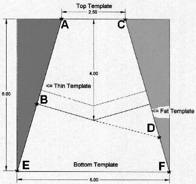
The top template will follow the exact shape of the foam core that we wish to emulate. Since the foam core is going to be covered with1/16 thickness balsa, we must make the foam core 1/16 smaller than the finished product on all sides. Having traced out the shape of the upper surface we must now employ some of our high school geometry to figure out with the bottom template should look like. In essence, we have to project the sides to a shape that is considerably larger than that which we will eventually have left after the cutting has taken place.
In the diagram opposite, the width of the top template (A-C) is shown as 2.5-in. This is the actual size of the finished core. But, the bottom template (E-F) has to be a full 6.0-in. wide. Of course, that is much wider than the final core, but this is where the high school geometry comes in and forces us to take this preliminary step. The "thin side" template (A-B) will also be the actual size of the finished product, while the "fat side" template (C-D) will have to be oversized as shown.
If you are having a slow day, you and your buddies can while away a few hours debating whether the step on a 36 inch float should be mid-way at 18 inches or whether the split should be 17 up front and 19 in the rear. Your call!
The measurements shown above are not absolute and are provided as a guide
only. You can get a usable "fat side" by simply adding 1-in. to the girth of the
bottom edge of the "thin side". If you want a more pronounced "Vee", then
increase the girth of the "fat side". Note that the outlines of the tops of the
"thin" and "fat" templates are identical. 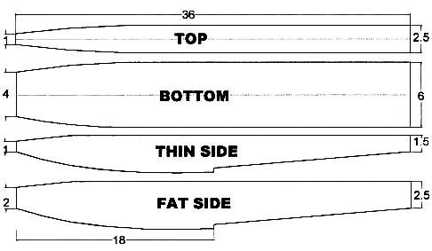
Once you have
your templates complete, you will need to drill a series of small holes along
the centerline of each template. Into these holes we will insert 2-in. nails
that will perforate the foam and hold templates in place while we complete our
cutting.
Make sure that you place these nails such that they do not snag the hot
wire when you cut.
Safety
The fumes generated when you use a hot wire to cut foam are hazardous to your health. Make sure you do the cutting operation in a well-ventilated place - it is not something that you want to do in your basement workshop - the smell alone will place great stress on your relationship with other family members.
Blank Cutting
You can use a band saw or a normal carpenter's saw to rough cut the basic shapes. You will find that the foam will create a lot of "dust" that has electrostatic properties that ensure that it will cling to every possible surface you can imagine and contaminate everything that you come into contact with for at least six months afterwards. By far the better route to go is the long hot wire cutter.
To start out, take sheets of white insulating foam that is two-in. thick, four feet wide and eight feet long. Take a yardstick and mark out blocks that are six inches wide by 40 inches long. We will need three of these basic blocks for each float.
We now need to laminate three of these 2-inch plates together. We must simply tack the three pieces together in such a way that the hot cutting wire will never come into contact with what ever material we use as glue. In essence we are going to run a bead along the 40-in. length, approximately 1-in. from the surface that we designate as the top of the float. We are going to glue them so that the pieces have the two-inch thickness facing upwards. The sheets need to be weighted down and left to cure overnight to make sure that the adhesive has set.
You can use epoxy, contact cement or foam glue for the lamination. Recently, I have been tending towards ProbondÓ, which is one of the newer foam glues that reacts with water and expands to fill in any voids in the foam. Use this glue sparingly and wet both foam surfaces to get the reaction started. Watch out for the almost unnoticeable fumes - they are not good for your health.
Core
Cutting 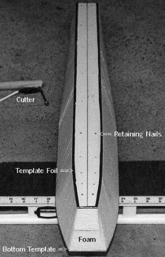
Take the first blank that is 6-in. by 6 in. by 40 in. and put the top and bottom templates in place using the retaining nails. Looking from the side, there should be a completely smooth surface. That is, the top and bottom templates have covered the two sandwich lines.
Plug in your short hot wire bow and use a scrap piece of foam to adjust the power setting until the wire moves at a slow but steady pace. Only practice will tell you which temperature is best. If the wire is too cold, it will drag and you will get a very sloppy cut. If it is too hot, every time you pause for even a microsecond, the overheated wire will melt too much foam and you will have a very pronounced ripple effect.
Draw the bow in a smooth, continuous motion keeping the wire at 90 degrees to both template edges and ensuring that it stays in contact with both the top and bottom templates. You do not want any lead or lag of the wire - keep a constant chord.
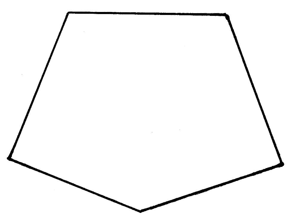
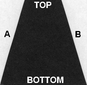
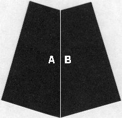
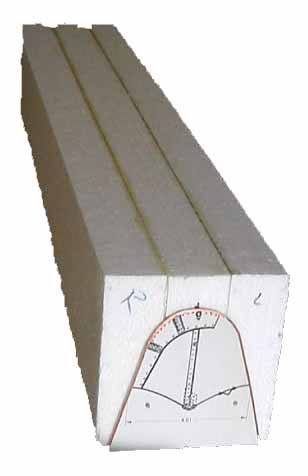
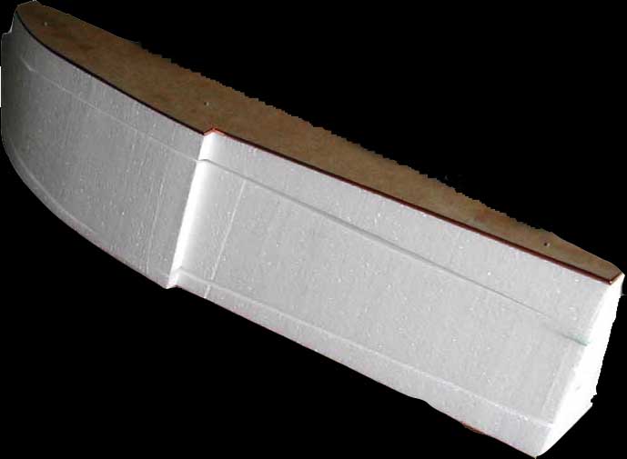
Do not force the wire through the foam. Let it find its own pace. Without having actually measured it, my guess is that the wire covers one inch in the standard three count - one hundred and one, one hundred and two, one hundred and three. Perform this operation on both sides. You should wind up with the four-sided wedge shape shown at the right.
In rough numbers, it is about 2.5-in at the widest part of the top and
6-in. at the broadest part of the bottom. The wedge is 6-in. high front to
back. 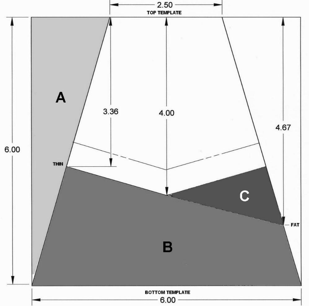
The first two first two cuts will have removed the material shown as "A" on the left side - and its mirror image on the right.
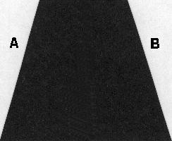
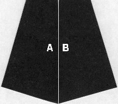
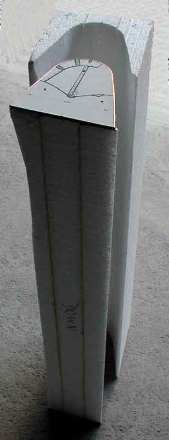
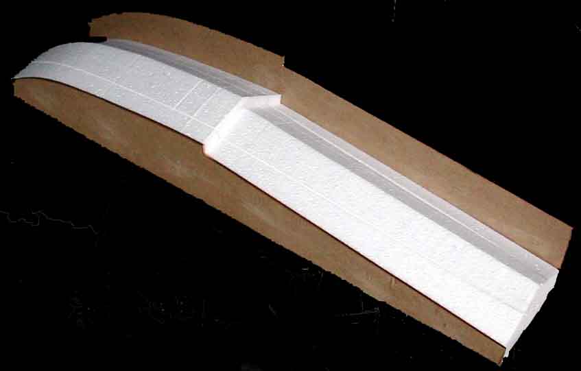
Now nail on the "thin and fat side" templates so that the top surfaces are flush with the top of the foam blank.
The "thin side" template is shown being 3.36-in at the deepest part of the step, while the "fat side" template is marked as 4.67-in.
Make your first side cut being especially careful to turn the corner at the step quite smoothly. This will remove the four-sided foam wedge at the very bottom shown as "B".
Now reverse the two side templates and make the fourth cut. It will remove the
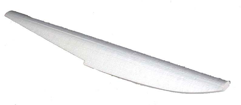
If all went well, you now have a perfect "Vee" shape bottom the whole length of the float. The final cuts are at the front and back to adjust the 40-in. length down to 36 in. or what ever final length you desire, being careful to keep in mind the critical position of the step at the center of gravity of the aircraft.
Alternate Method
Like just about everything in life, there is more than one
way to do things. John Hawkins of the Halifax Radio Control Club, which boasts a
formidable float flying capability at Meisner Lake, has suggested another
method.
Start out with a 6-in. by 6-in. by 40-in. blank. Using the same method as above, cut out the "wedge" shape using the top and bottom templates. John has a much more elegant term than wedge that reflects his Maritimes background - he calls it a tumblehome, which translates as, "the inward curve of a ship's topsides".
Note: All cross-sections shown are at the widest, deepest part of the step.
The great advantage of John's method is that the side templates are both the same size; to wit, the outline of the final shape you want. Ergo, there is less geometry involved - no need to calculate a "fat side".
Where side templates A and B are the same size, make the left and right
cuts. The "tumblehome" will now be about 4-in. tall at the deepest part of the
step.
Next comes the ingenious part.
Using your favourite method, cut the whole thing in half vertically, stem to stern.
Given the flat top and bottom, this could be accomplished with a band saw.
Equally, if you don't like flying foam particles, the long bow hot wire works well. You will have to make two templates that can be nailed to the front and back to given you are perfectly square line to follow.
Using your foam glue of choice, reverse the two sides and glue the former outside edges A and B together.
Isn't that just the neatest trick?
Who would have thought of that in a month of Sundays?
Finally, take the chevron-shaped top off to create a perfectly flat
float.
Are there any other methods out there?
Attachment Plates
Regardless of the geometry of your undercarriage, it has to be attached to the float. The foam is too soft so we must use a 1/4-in. plywood attachment plate. It has to have enough surface area such that it will stay glued to the foam when subjected to shock and it has to be thick enough to hang onto the fastenings used. Those who have been flying for some time acknowledge the fact that they are going to crash. Equally, they have absorbed the lesson that tanks don't fly. That is, by the time you build up an aircraft to the point that it will not be hurt in a crash, it is so heavy that it won't fly.
Bindings
In the early days of skiing, those long planks were lashed to the skier's boot with leather thongs. When the skier crashed, the skis did not come off, the skier just broke a leg. Think of your float as a ski. It has a lot of surface area and is long enough to have quite a moment arm.
When you crash into the water at speed, something is going to
break - all that is left is our choice of what we would like to crack first.
I would like the float to separate from the aircraft when push comes to shove. It is easier to fix a float than a wing!
So, you can nail your undercarriage to the attachment plate using wood screws. They are likely to rip out under force. Or, you can put blind nuts under the plywood and use 4-40 metal bolts. This combination is not as likely to tear out.
Jack Humphreys suggests that the best bet is to use blind nuts and nylon 4-40 wing bolts, as supplied by SIGÔ part number SIGSH172. All things being equal, your biggest problem will be digging out sheered nylon shanks. (Tip: Take a flat edged soldering tip and melt in a slot in the nylon remainder and then unscrew using a small flat head screwdriver. If all else fails, bore out the nylon with a drill bit.)
If your undercarriage uses 5/32-in. wire, then a neat binding to use is nylon nose blocks and a central collet. Bill Shedden points out that you should grind the collet station flat on the axle to prevent "pops".
A typical binding will involve 4 blind nuts. To stop epoxy and/or contact cement getting into the nuts do this. Create circles using a paper punch and a scrap of covering film. Tack the circles to the bottom of each blind nut. When you epoxy in the attachment plate, the film will keep the epoxy out. Cut a piece of paper to the exact size of the attachment plate and use a pencil to mark the top of each nut. Cut strips of covering film about 4-in. by 3/8-in. and tack width-wise over the top of the nuts so that whiskers project over each side. When you lay in the top balsa sheet, the film whiskers will show the axis of the nuts, while the paper model will confirm the fore and aft locations. Use an awl to punch out the holes in the top balsa sheet.
Options
Like everything else in life, there are the basic and deluxe models. If you are just going to try float flying once or twice, then you can make up some basic floats. They may last a couple of seasons. The basic float is made by cutting the cores, sheeting them with balsa, gluing on some attachment plates for undercarriage and rudders then covering with film.
The cumulative effect of the buffeting from high speed on the water, and the odd missed landing, can cause a lot of sheer stresses that tend to open things up over time. More durable floats recess the attachment plates into the foam tops, use "rip away" mounting bolts, stiffen the rear deck, spread landing loads, use a step plate to protect the "Vee" and are covered with fibreglass to provide a durable cover. Bill Shedden prefers SIG KoverallÓand dope to the fibreglass technique. Hereinafter, the optional features will be marked as such.
Stiffening Spline (Optional)
Some people believe that it is necessary to have a stiffener running down
the rear two-thirds of the top part of the float. Some folks like to put in
relatively heavy spruce wood strip that is 1 in. wide by 1/4-in. thick by 24-in.
long. They lay in this spline so that the thickness is parallel to the top of
the float. They use this thick horizontal spine as both the stiffener and a
place to which one can screw in the under carriage bindings. This tends to be a
relatively heavy installation, and adds weight to the rear of the float. Skip
Pothier's much lighter alternative is to lay in a vertical spline of balsa wood
that is 24-in. long by 3/4-in. deep by 1/4-in. thick. 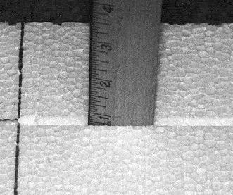
We will discuss the balsa spline. This spline serves two basic purposes. First, it acts as the stiffener to prevent the back end of the float snapping off at the step, second it acts as a method of distributing landing load shock from the two under carriage plywood blocks. It is been noticed that after a couple years of flying that the landing shock creates absolutely incredibly small hairline fractures where two pieces of disparate materials meet. Small amounts of moisture seem to get into these cracks and, although you don't notice it immediately, over a period of time they cause the wood to swell and the crack enlarges. By dissipating the landing load shock it is hoped that these hairline fractures can be avoided.
There are three ways in which we can run the 24-in. long by 3/4-in. deep by 1/4-in. wide trench down the top back of the float. First we can use a router with a straight-line guide. This method is effective, quick and extremely messy. It is messy in the sense that you will be covered in particles of foam from head to foot. If you are lucky enough to own a table saw, then a couple of passes with a table saw will do a beautiful job with very little mess. Most likely the easiest method is to use a soldering iron with an existing tip running it down a straight edge and hoping that you can maintain a 3/4-in. inch depth.
A clever way of using a WellerÔ - type soldering iron is to remove the existing solder tip and replace it with a length of 110-volt household solid copper wire bent in a square "U" shape of the trough that you want to cut out of the foam. The added tricks are to create templates or guides to give you straight lines and to control the depth of the cut. So, if you want to cut a trough one inch deep and your template/guide is 3/16" plywood, then the copper wire has to be 1 and 3/16 inches deep. It takes no time at all to cut a channel. Use masking tape to tack the template/guide to the foam while you are "soldering the foam".
Sanding
Because we are using the inexpensive insulating foam, the cut cores will be a bit rough. Take a sanding block with 80-grade paper and roughly sand off the sides. If there are any huge craters, fill them with lightweight vinyl spackling. Sand to taste, but as Skip indicates, you are going to paint on contact cement, so a mirror finish is not required.
Measurement
You will have to determine the stations on the top of the float where the front and rear undercarriage securing points will be located. Once this is been determined, cut out that mounting station as a square of 1/4-in. plywood such that it almost covers the top of the float side to side. In general, this piece of plywood is about a 1 3/4-in. square.
Cut out matching 1/4-in. notches in the stiffener to receive the plywood attachment plates.
Using the short hot wire bow and two scrap templates one each side, cut out a matching 1/4-in. deep saddle.
Before you glue in the stiffener, run a bead of thin CA down the 3/4-in. side of the spline to greatly increase its strength with paying a weight penalty. Use a thin coat of epoxy to glue in the stiffening spline into the rear 24-in. of the top of the float.
Glue the square plywood mounting platforms into the foam saddle such that the tops are perfectly flush with the top of the float. Allow the epoxy glue to set. Use a 1/16-inch balsa sheet to cover all four sides of the foam core.
Adhesives for Balsa Sheeting the Foam Cores
There are four basic ways to attach balsa to foam. Two of these methods are best reserved for sheeting wing cores, while the others work well for float cores. Sorghum gum is the proven, ancient and honorable way. Epoxy is an equally proven solution. However, both of these methods assume that you are going to be able to cover the sheeting material with the discarded foam saddles and then apply uniform weight for a protracted period of time (overnight). Vacuum bagging is a superior method to weight. The complex, four sided cuts of the float cores do not leave good matching saddles and the uneven and rounded surfaces make it very hard to weight the sheets down overnight - an easier solution is recommended. Use contact cement.
Contact cements come in three basic flavours. Paint-on water-based or solvent-based, and spray on. Solvents are not good for your health in poorly ventilated spaces - since they also eat foam, they are rejected. There have been reports on the Net that the spray-on contact cements (such as 3M 77Ô) can cause the balsa to delaminate in the hotter temperatures of mid-summer.
In essence, Lepage'sÔ water-based contact cement is the logical winner. It is easy to find, inexpensive, dries fairly quickly, doesn't stink up the house, gives a good bond and cleans up easily. Who could ask for more?
Balsa Sheet Laminations
If the sides are bigger than the width of your balsa sheeting, it is import to make up the laminations before you sheet. Lay the two pieces side by side on a perfectly flat surface - glass is a good choice. Cover the surface with waxed paper. Make sure the two sides line up exactly. Sand the sides with a long sanding block until you have a perfect mate. In the worst case, overlap the two sheets and use a steel edge to cut through both surfaces at once. Once the sides are true, you can use either thin CA or carpenter's glue to complete the job. Weight the sheets down so they cannot move. In either case, glue from the side that will be towards the foam core - you do not want a hard glue scab on the outer surface, as it is hard to sand and will result in an uneven finished surface. Be especially careful with thin CA - if it wicks through to the outer side, it will form a sheet of concrete that just cannot be sanded. There is no preferred sequence for covering the sides.
Cut the balsa sheet to a slightly larger piece than is required to cover the surface. Brush the contact cement on the foam and onto the balsa sheet. Allow both surfaces to dry as per the instructions. Carefully place the balsa sheet on the foam surface. Note that we will have only one try as the contact cement will grab the balsa and it is impossible to take it off without cracking it. Trim the oversize balsa with a razor knife so that the edges are flush with the foam core. Attach the other surfaces in sequence until all for sides have been covered. Leave the front and back ends bare for the moment.
Rear Plate
Take the back and of the float and traced the outline on a sheet of light ply. The light ply should be about 1/16th inch thickness. Use a hobby knife or coping saw to cut out this rear plywood shape. Attach it to the back the float with contact cement. This plywood is needed to secure the screws that will be used for the rudders.
Nose Blocks
The noses of the float will be covered with a block of balsa wood, but before we finish the float we need to have some idea of how the whole affair balances against the centre of gravity of the aircraft with floats mounted. We will be adding lead weight, probably to the noses of the floats and we will then conceal this lead weight by hollowing out the balsa blocks that we will eventually sand to a desirable shape. [Hint: Gouge out the foam at the float tip and glue in the butt of a plastic top of a CA cover. Add small fishing weights until balance is achieved, using cotton wool as a temporary plug. When satisfied, remove the cotton wool and pour in epoxy to secure the load. Glue on the hollowed out balsa nose to conceal.]
Attachment Plate Anchor Dowels (Optional)
When you come in for a landing, as soon as the floats touch the water a tremendous amount of drag is induced. That translates into a sheer force that wants to send the attachment plates to the back of the float and also tends to introduce a rotational force that wants to lift the plates off the float. Over time, this can introduce micro cracks. Both Phil Peloquin and Skip Pothier recommend that you install anchor dowels to avoid this.
Figure our where you will insert your undercarriage screws or bolts and look for some space where you can drill down 1/4 or 3/8-in. vertical shafts. Depending on your choice, you can use two to four of these dowel receptacles. The shafts should be 1 1/2 to 2 inches in depth. After you have epoxied the attachment plates onto the float, epoxy these anchor dowels in place. They will make sure that the sheering forces do not dislodge the attachment plates.
Step Plate (Optional) 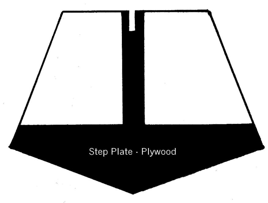
As Phil
Peloquin points out, when all is said and done, it all happens on the step. This
area takes the most punishment and some reinforcement might be appropriate. The
simplest method is to insert a light plywood step plate.
Place a carpenter's saw against the vertical surface of the step with the saw teeth up. Cut a narrow slot up into the float about one inch deep at the "Vee" of the step. Take a piece of paper and insert it into the slot. Trace out the pattern.
At the top centre opposite the "Vee" point, put a 1-inch vertical tongue on it. Notch the top of the tongue so that it will mate with the 3/4-inch balsa stiffener. Transfer the pattern to light plywood that matches this shape and epoxy it in place.
Anti-Crush Panels (Optional)
Bill Shedden likes to build bigger planes. With the heavier weight, there is the concern that sitting the plane on the ground will lead to damage to the float bottoms where the weight is concentrated, namely the step. Equally, when start or we tinker with engine, we tend to lean on the aircraft: all such forces transfer down to the step area. Bill likes to put in lite plywood panels that are about 2-in. wide, extend the width of the float, are just forward of and tie back into the reinforcing step plate. These panels replace about 2 inches of balsa sheet.
Steering Control Guides (Optional)
You might need to sink a couple of 1/4-inch dowel plugs into the rear deck of the floats to install small metal guides for steering rods or cables. Epoxy them in before you cover the top deck with balsa sheet.
Covering
If electing to cover with fibreglass cloth, this procedure is explained in depth in the separate article entitled,
"In Praise of Water-based Polyurethane Varnish".
 |
 |
 |
The fundamental difference cutting this style of foam core is the very
first step. Templates of the same size and shape are nailed to the back
and front of the foam core blank. The hot wire is run around the templates
to cut out the equivalent of a "railroad tunnel". The "railroad
tunnel" is tacked back onto the hump shape and the fat and thin side
templates are tacked onto the outer sides of the "railroad tunnel".
 |
 |
 |
Once the first cut is made, the fat and thin side templates are reversed and a second cut made to get a perfect "Vee". The result is shown above.
Click here to return to the Carl Goldberg style.
Overview of Setup and Flying
You cannot go wrong by having another look at the article, "The Basics of Float Flying". This prose summarizes the collective wisdom of those who have already made all the mistakes and are busy inventing new ones!
Detailed Guide by Skip Pothier
Having taken you through all the above, let me admit that Skip has done a much better job at explaining the nitty-gritty in a very well-written article that you should read. Skip assumes that you have a pair of foam cores, then leads you through the steps to finish a perfect set of floats. Click here to read his work entitled, "Building Those First Foam Core Floats".
[Revision # 22 dated 22 May 2003]